|
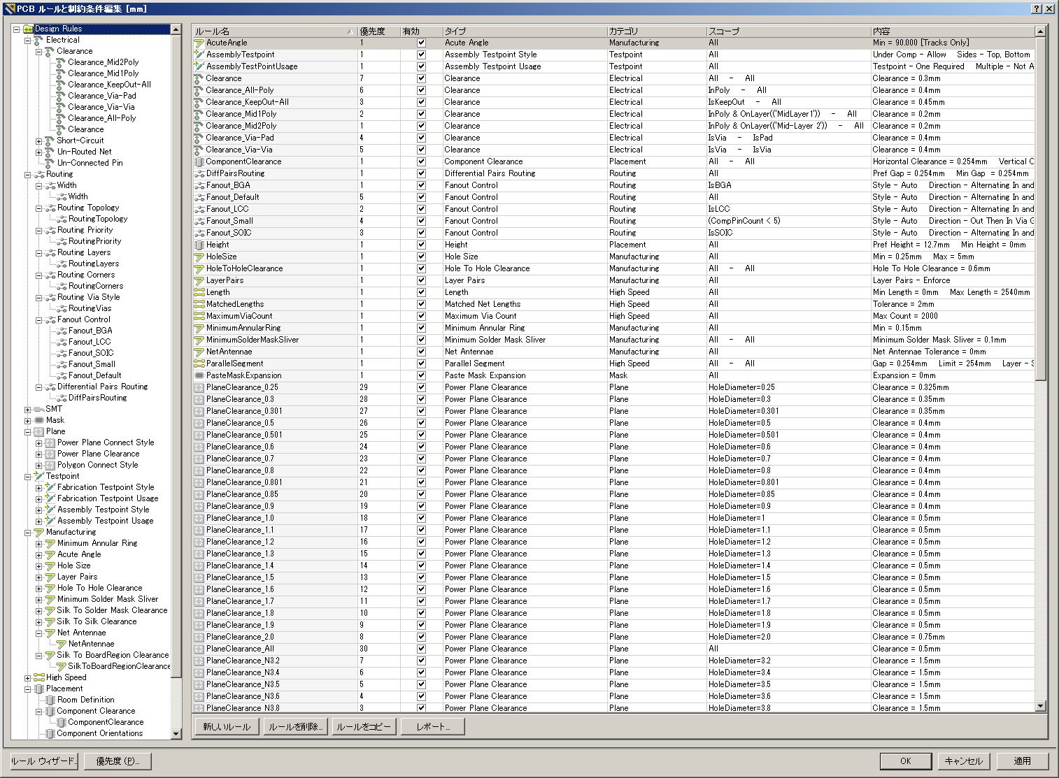
■ Altium Designer DRC - Design Rule Check - |
白 ■ インストール直後の状態 ピンク ■ C_Cテンプレート4層基板用で追加変更されている項目 | |||||
| - A - | ||||||
| ルール名(名称) | 優先度 | 有効 | タイプ | カテゴリ | スコープ(クエリ) | 内容(制約条件) |
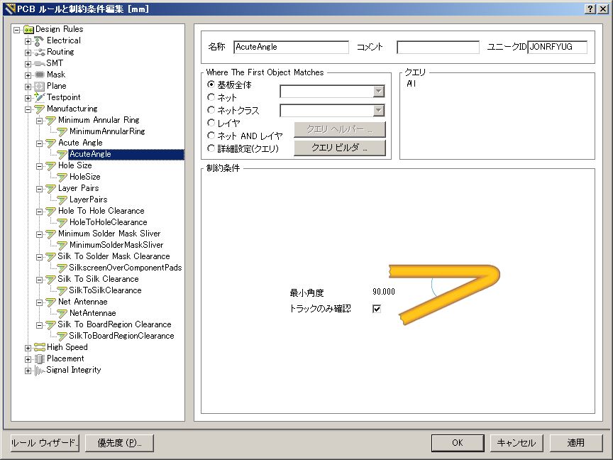
| Acute Angle | Manufacturing | All | Min = 90.000 [Tracks Only] | |||
|
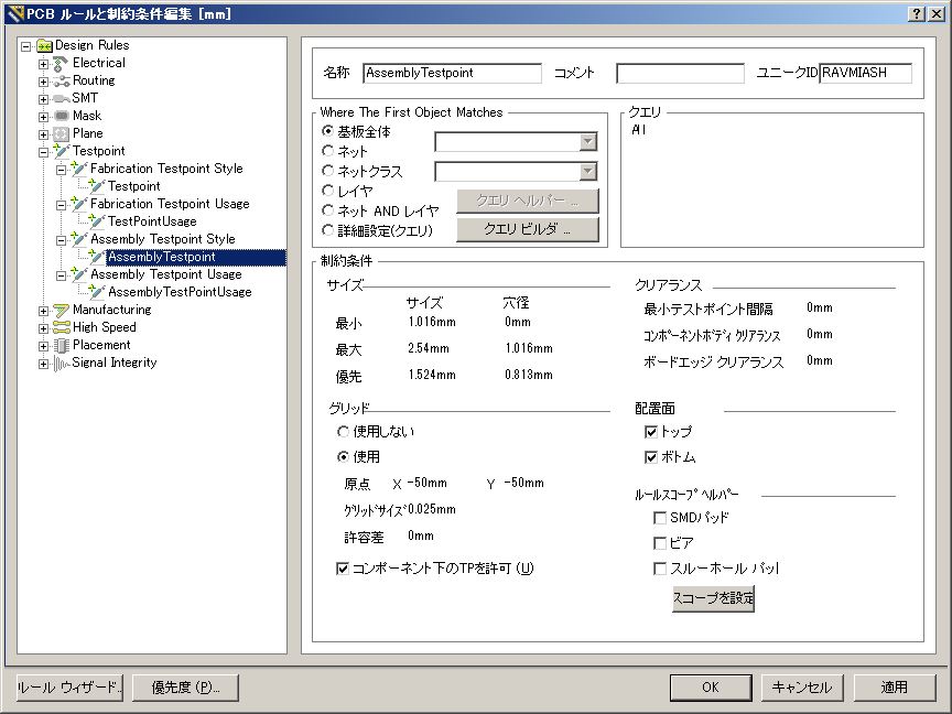
AssemblyTestpoint |
1 | True | Assembly Testpoint Style | Testpoint | All |
Under Comp - Allow |
|
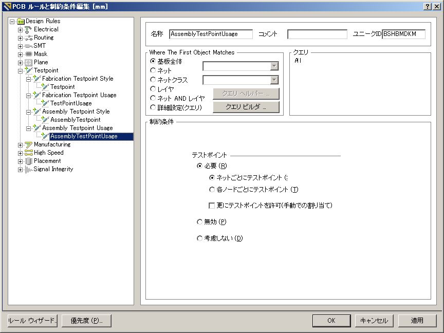
AssemblyTestPointUsage |
1 | True | Assembly Testpoint Style | Testpoint | All |
Testpoint - One Required |
| - C - | ||||||
| ルール名(名称) | 優先度 | 有効 | タイプ | カテゴリ | スコープ(クエリ) | 内容(制約条件) |
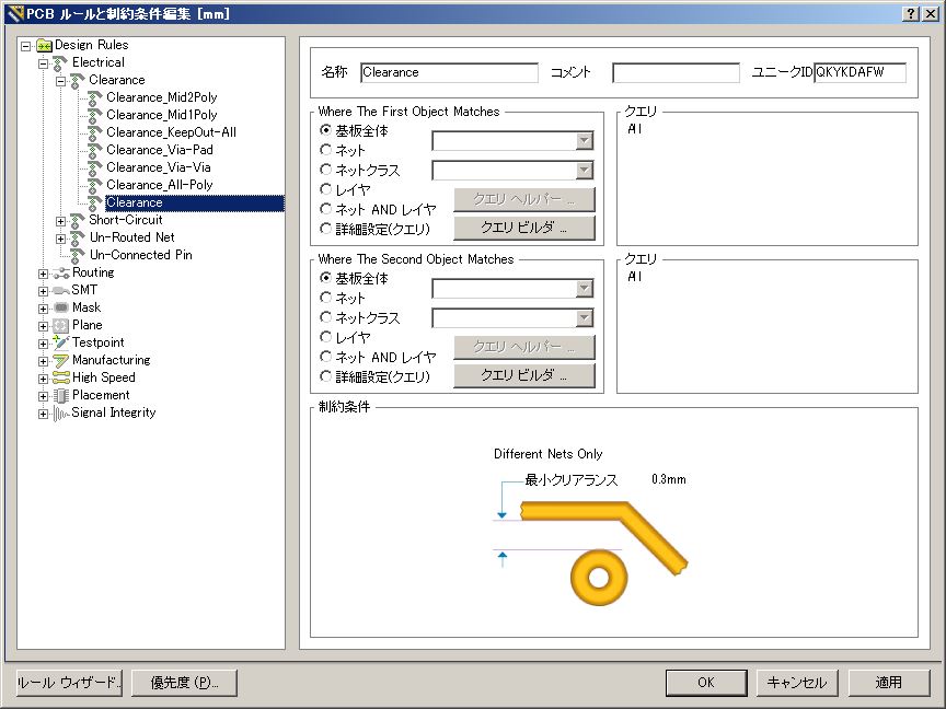
| 1 | True | Clearance | Electrical | All - All | Clearance = 0.254mm | |
| 7 | Clearance = 0.3mm | |||||
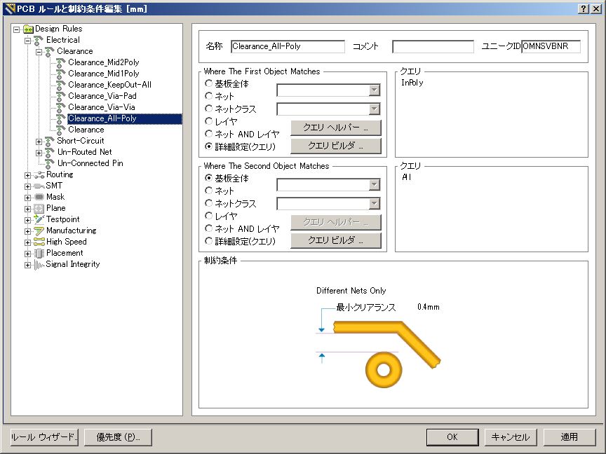
| 6 | True | Clearance | Electrical | InPoly - All | Clearance = 0.4mm | |
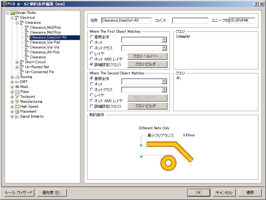
| 3 | True | Clearance | Electrical | IsKeepOut - All | Clearance = 0.45mm | |
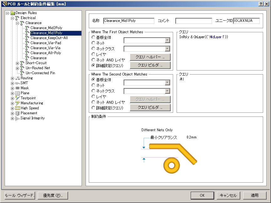
| 2 | True | Clearance | Electrical | InPoly & OnLayer(('MidLayer1')) - All | Clearance = 0.2mm | |
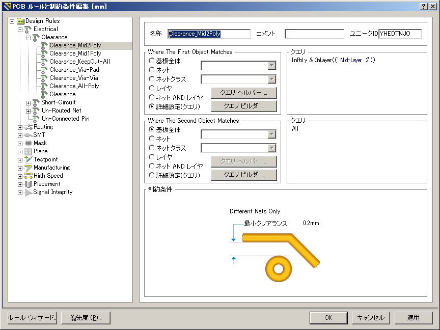
| 1 | True | Clearance | Electrical | InPoly & OnLayer(('MidLayer2')) - All | Clearance = 0.2mm | |
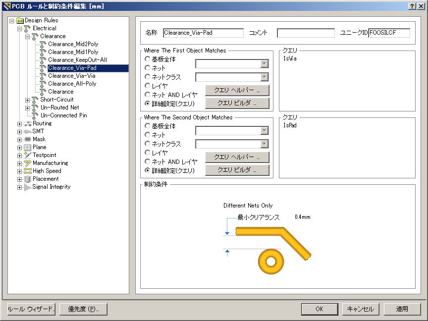
| 4 | True | Clearance | Electrical | IsVia - IsPad | Clearance = 0.4mm | |
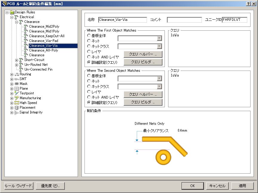
| 5 | True | Clearance | Electrical | IsVia - IsVia | Clearance = 0.4mm | |
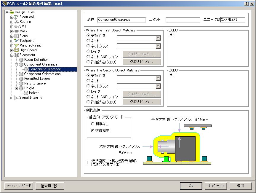
| 1 | True | Component Clearance | Placement | All - All | Horizontal Clearance = 0.254mm Vertical Clearance = 0.254mm |
|
| - D - | ||||||
| ルール名(名称) | 優先度 | 有効 | タイプ | カテゴリ | スコープ(クエリ) | 内容(制約条件) |
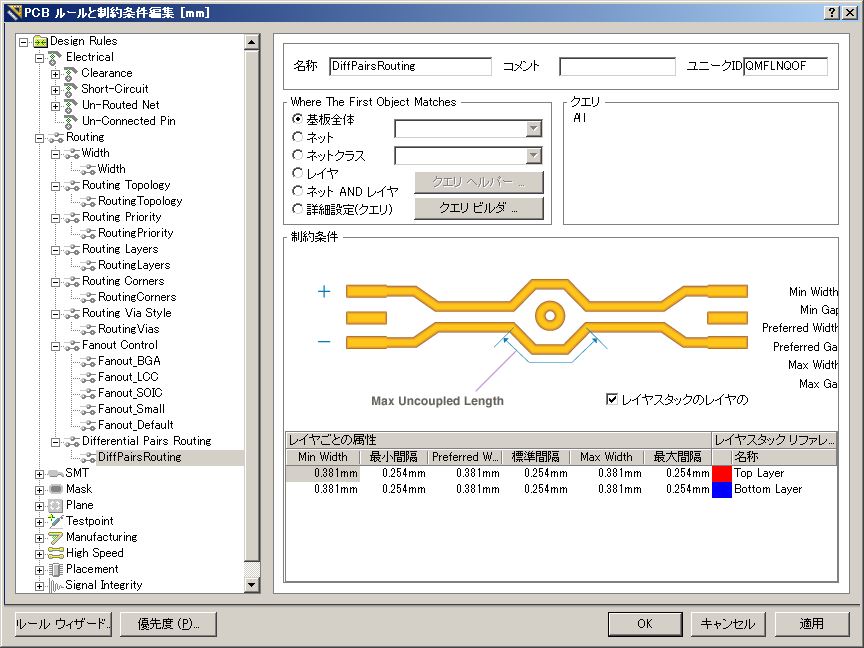
| 1 | True | Differential Pairs Routing | Routing | All | Pref Gap = 0.254mm Min Gap = 0.254mm Max Gap = 0.254mm Pref Width = 0.381mm Min Width = 0.381mm Max Width = 0.381mm |
|
| - F - | ||||||
| ルール名(名称) | 優先度 | 有効 | タイプ | カテゴリ | スコープ(クエリ) | 内容(制約条件) |
|
FabricationTestpoint |
1 | True | Fabrication Testpoint Style | Testpoint | All | Under Comp - Allow Sides - Top, Bottom Pref Size = 1.524mm Pref Hole Size = 0.813mm Using Grid = Yes Grid = 0.025mm Grid Tolerance = 0mm |
| NONE | ||||||
|
FabricationTestPointUsage |
1 | True | Fabrication Testpoint Usage | Testpoint | All | Testpoint - One Required Multiple - Not Allowed |
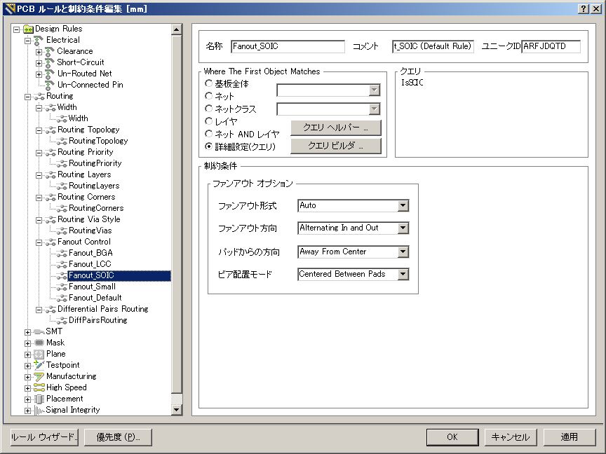
| 1 | True | Fanout Control | Routing | IsBGA | Style - Auto Direction - Alternating In and Out Via Grid = 0.025mm |
|
| 1 | True | Fanout Control | Routing | All | Style - Auto Direction - Alternating In and Out Via Grid = 0.025mm |
|
| 2 | True | Fanout Control | Routing | All | Style - Auto Direction - Alternating In and Out Via Grid = 0.025mm |
|
| 4 | True | Fanout Control | Routing | All | Style - Auto Direction - Alternating In and Out Via Grid = 0.025mm |
|
| 3 | True | Fanout Control | Routing | All | Style - Auto Direction - Alternating In and Out Via Grid = 0.025mm |
|
| - H - | ||||||
| ルール名(名称) | 優先度 | 有効 | タイプ | カテゴリ | スコープ(クエリ) | 内容(制約条件) |
| 1 | True | Height | Placement | All | Pref Height = 12.7mm Min Height = 0mm Max Height = 25.4mm |
|
| 1 | True | Hole Size | Manufacturing | All | Min = 0.025mm Max = 2.54mm |
|
| Min = 0.25mm Max = 5mm |
||||||
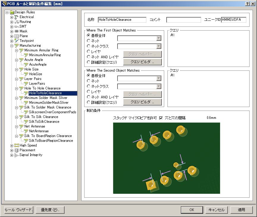
| 1 | True | Hole To Hole Clearance | Manufacturing | All | Hole To Hole Clearance = 0.254mm |
|
| Hole To Hole Clearance = 0.6mm |
||||||
| - L - | ||||||
| ルール名(名称) | 優先度 | 有効 | タイプ | カテゴリ | スコープ(クエリ) | 内容(制約条件) |
| 1 | True | Layer Pairs | Manufacturing | All | Layer Pairs - Enforce | |
| 1 | True | Length | High Speed | All | Min Length = 0mm Max Length = 2540mm |
|
| - M - | ||||||
| ルール名(名称) | 優先度 | 有効 | タイプ | カテゴリ | スコープ(クエリ) | 内容(制約条件) |
| 1 | True | Matched Net Lengths | High Speed | All | Tolerance = 2mm | |
| 1 | True | Maximum Via Count | High Speed | All | Max Count = 2000 | |
| 1 | True | Minimum Annular Ring | Manufacturing | All | Min = 0.15mm | |
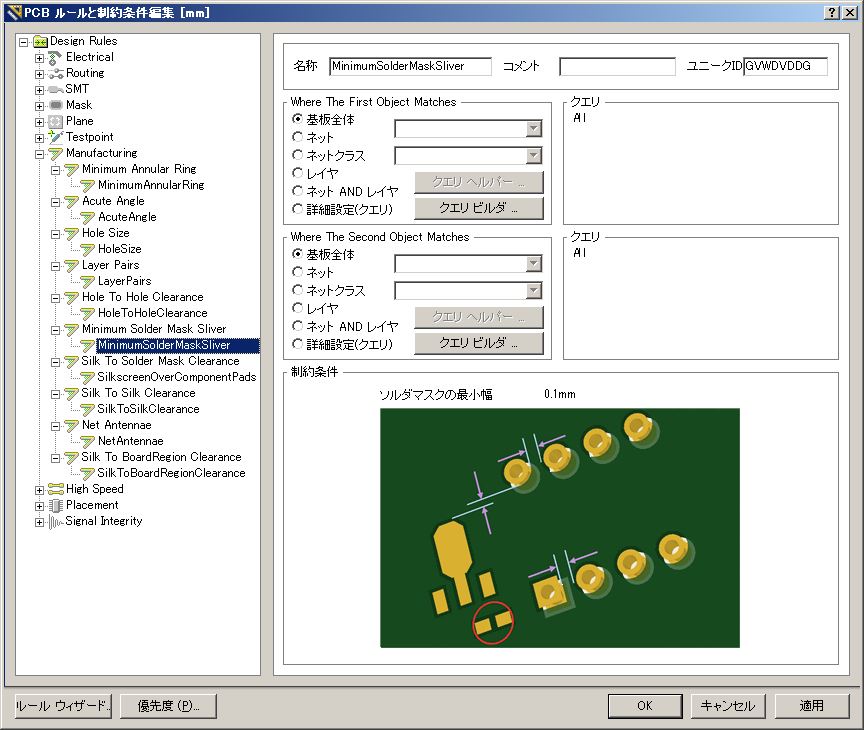
| 1 | True | HeightMinimum Solder Mask Sliver | Manufacturing | All - All | Minimum Solder Mask Sliver = 0.254mm | |
| Minimum Solder Mask Sliver = 0.1mm | ||||||
| - N - | ||||||
| ルール名(名称) | 優先度 | 有効 | タイプ | カテゴリ | スコープ(クエリ) | 内容(制約条件) |
| 1 | True | Net Antennae | Manufacturing | All | Net Antennae Tolerance = 0mm | |
| - P - | ||||||
| ルール名(名称) | 優先度 | 有効 | タイプ | カテゴリ | スコープ(クエリ) | 内容(制約条件) |
| 1 | True | Parallel Segment | High Speed | All - All | Gap = 0.254mm Limit = 254mm Layer - Same Layer |
|
| 1 | True | Paste Mask Expansion | Mask | All | Expansion = 0mm | |
|
PlaneClearance |
1 | True | Power Plane Clearance | Plane | All | Clearance = 0.508mm |
| NONE | ||||||
| 29 | True | Power Plane Clearance | Plane | HoleDiameter=0.25 | Clearance = 0.325mm | |
| 28 | True | Power Plane Clearance | Plane | HoleDiameter=0.3 | Clearance = 0.35mm | |
| 27 | True | Power Plane Clearance | Plane | HoleDiameter=0.301 | Clearance = 0.35mm | |
| 26 | True | Power Plane Clearance | Plane | HoleDiameter=0.5 | Clearance = 0.4mm | |
| 25 | True | Power Plane Clearance | Plane | HoleDiameter=0.501 | Clearance = 0.4mm | |
| 24 | True | Power Plane Clearance | Plane | HoleDiameter=0.6 | Clearance = 0.4mm | |
| 23 | True | Power Plane Clearance | Plane | HoleDiameter=0.7 | Clearance = 0.4mm | |
| 22 | True | Power Plane Clearance | Plane | HoleDiameter=0.8 | Clearance = 0.4mm | |
| 21 | True | Power Plane Clearance | Plane | HoleDiameter=0.801 | Clearance = 0.4mm | |
| 20 | True | Power Plane Clearance | Plane | HoleDiameter=0.85 | Clearance = 0.4mm | |
| 19 | True | Power Plane Clearance | Plane | HoleDiameter=0.9 | Clearance = 0.4mm | |
| 18 | True | Power Plane Clearance | Plane | HoleDiameter=1 | Clearance = 0.5mm | |
| 17 | True | Power Plane Clearance | Plane | HoleDiameter=1.1 | Clearance = 0.5mm | |
| 16 | True | Power Plane Clearance | Plane | HoleDiameter=1.2 | Clearance = 0.5mm | |
| 15 | True | Power Plane Clearance | Plane | HoleDiameter=1.3 | Clearance = 0.5mm | |
| 14 | True | Power Plane Clearance | Plane | HoleDiameter=1.4 | Clearance = 0.5mm | |
| 13 | True | Power Plane Clearance | Plane | HoleDiameter=1.5 | Clearance = 0.5mm | |
| 12 | True | Power Plane Clearance | Plane | HoleDiameter=1.6 | Clearance = 0.5mm | |
| 11 | True | Power Plane Clearance | Plane | HoleDiameter=1.7 | Clearance = 0.5mm | |
| 10 | True | Power Plane Clearance | Plane | HoleDiameter=1.8 | Clearance = 0.5mm | |
| 9 | True | Power Plane Clearance | Plane | HoleDiameter=1.9 | Clearance = 0.5mm | |
| 8 | True | Power Plane Clearance | Plane | HoleDiameter=2.0 | Clearance = 0.75mm | |
| 30 | True | Power Plane Clearance | Plane | All | Clearance = 0.5mm | |
| 7 | True | Power Plane Clearance | Plane | HoleDiameter=3.2 | Clearance = 1.5mm | |
| 6 | True | Power Plane Clearance | Plane | HoleDiameter=3.4 | Clearance = 1.5mm | |
| 5 | True | Power Plane Clearance | Plane | HoleDiameter=3.5 | Clearance = 1.5mm | |
| 4 | True | Power Plane Clearance | Plane | HoleDiameter=3.6 | Clearance = 1.5mm | |
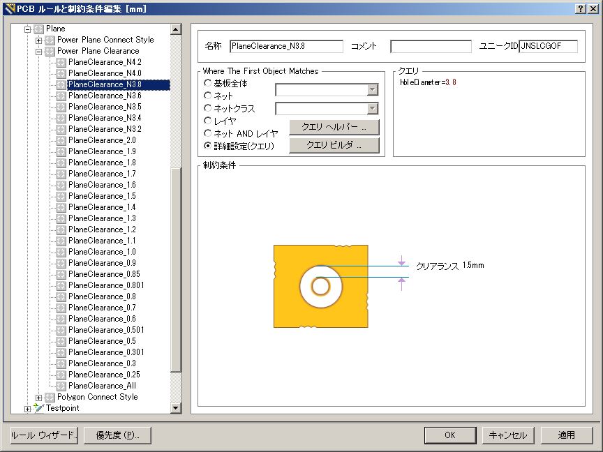
| 3 | True | Power Plane Clearance | Plane | HoleDiameter=3.8 | Clearance = 1.5mm | |
| 2 | True | Power Plane Clearance | Plane | HoleDiameter=4.0 | Clearance = 1.5mm | |
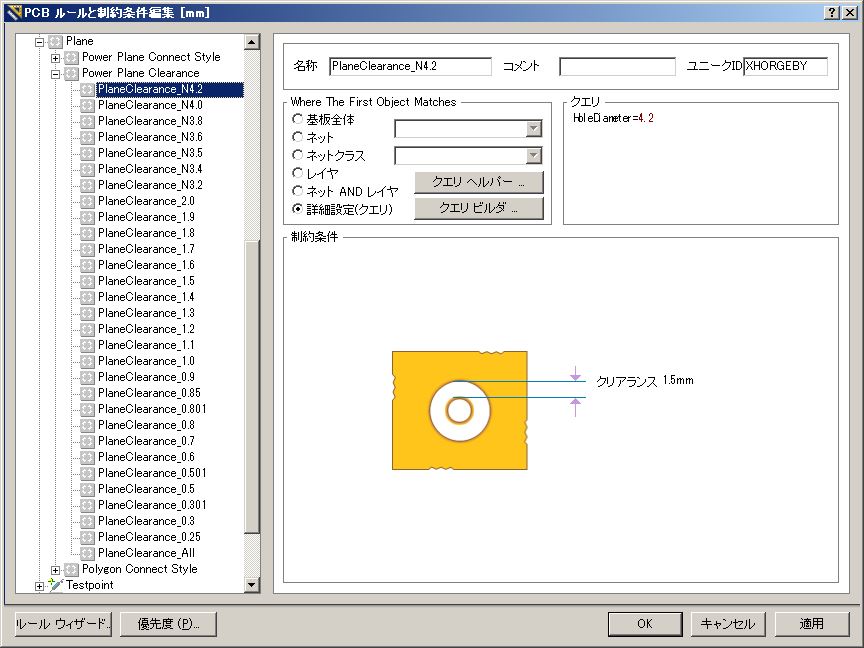
| 1 | True | Power Plane Clearance | Plane | HoleDiameter=4.2 | Clearance = 1.5mm | |
|
PlaneConnect |
1 | True | Power Plane Connect Style | Plane | All | Style - Relief Connect Expansion =
0.508mm Width = 0.254mm Gap = 0.254mm # Entries = 4 |
| NONE | ||||||
| 23 | True | Power Plane Connect Style | Plane | HoleDiameter=0.25 | Style - Direct Connect | |
| 22 | True | Power Plane Connect Style | Plane | HoleDiameter=0.3 | Style - Direct Connect | |
| 21 | True | Power Plane Connect Style | Plane | HoleDiameter=0.301 | Style - Relief Connect Expansion =
0.25mm Width = 0.3mm Gap = 0.3mm #Entries = 4 |
|
| 20 | True | Power Plane Connect Style | Plane | HoleDiameter=0.5 | Style - Relief Connect Expansion =
0.25mm Width = 0.3mm Gap = 0.3mm #Entries = 4 |
|
| 19 | True | Power Plane Connect Style | Plane | HoleDiameter=0.501 | Style - Relief Connect Expansion =
0.25mm Width = 0.3mm Gap = 0.3mm #Entries = 4 |
|
| 18 | True | Power Plane Connect Style | Plane | HoleDiameter=0.6 | Style - Relief Connect Expansion =
0.25mm Width = 0.3mm Gap = 0.3mm #Entries = 4 |
|
| 17 | True | Power Plane Connect Style | Plane | HoleDiameter=0.7 | Style - Relief Connect Expansion =
0.25mm Width = 0.3mm Gap = 0.3mm #Entries = 4 |
|
| 16 | True | Power Plane Connect Style | Plane | HoleDiameter=0.8 | Style - Relief Connect Expansion =
0.3mm Width = 0.3mm Gap = 0.3mm #Entries = 4 |
|
| 15 | True | Power Plane Connect Style | Plane | HoleDiameter=0.801 | Style - Relief Connect Expansion =
0.3mm Width = 0.3mm Gap = 0.3mm #Entries = 4 |
|
| 14 | True | Power Plane Connect Style | Plane | HoleDiameter=0.85 | Style - Relief Connect Expansion =
0.3mm Width = 0.3mm Gap = 0.3mm #Entries = 4 |
|
| 13 | True | Power Plane Connect Style | Plane | HoleDiameter=0.9 | Style - Relief Connect Expansion =
0.3mm Width = 0.3mm Gap = 0.3mm #Entries = 4 |
|
| 12 | True | Power Plane Connect Style | Plane | HoleDiameter=1.0 | Style - Relief Connect Expansion =
0.3mm Width = 0.5mm Gap = 0.3mm #Entries = 4 |
|
| 11 | True | Power Plane Connect Style | Plane | HoleDiameter=1.1 | Style - Relief Connect Expansion =
0.35mm Width = 0.5mm Gap = 0.3mm #Entries = 4 |
|
| 10 | True | Power Plane Connect Style | Plane | HoleDiameter=1.2 | Style - Relief Connect Expansion =
0.4mm Width = 0.5mm Gap = 0.3mm #Entries = 4 |
|
| 9 | True | Power Plane Connect Style | Plane | HoleDiameter=1.3 | Style - Relief Connect Expansion =
0.45mm Width = 0.5mm Gap = 0.3mm #Entries = 4 |
|
| 8 | True | Power Plane Connect Style | Plane | HoleDiameter=1.4 | Style - Relief Connect Expansion =
0.5mm Width = 0.6mm Gap = 0.3mm #Entries = 4 |
|
| 7 | True | Power Plane Connect Style | Plane | HoleDiameter=1.5 | Style - Relief Connect Expansion =
0.5mm Width = 0.6mm Gap = 0.3mm #Entries = 4 |
|
| 6 | True | Power Plane Connect Style | Plane | HoleDiameter=1.6 | Style - Relief Connect Expansion =
0.6mm Width = 0.7mm Gap = 0.3mm #Entries = 4 |
|
| 5 | True | Power Plane Connect Style | Plane | HoleDiameter=1.7 | Style - Relief Connect Expansion =
0.6mm Width = 0.7mm Gap = 0.3mm #Entries = 4 |
|
| 4 | True | Power Plane Connect Style | Plane | HoleDiameter=1.8 | Style - Relief Connect Expansion =
0.6mm Width = 0.8mm Gap = 0.3mm #Entries = 4 |
|
| 3 | True | Power Plane Connect Style | Plane | HoleDiameter=1.9 | Style - Relief Connect Expansion =
0.6mm Width = 0.8mm Gap = 0.3mm #Entries = 4 |
|
| 2 | True | Power Plane Connect Style | Plane | HoleDiameter=2.0 | Style - Relief Connect Expansion =
0.75mm Width = 1mm Gap = 0.3mm #Entries = 4 |
|
| 24 | True | Power Plane Connect Style | Plane | All | Style - Relief Connect Expansion =
0.8mm Width = 0.5mm Gap = 0.5mm #Entries = 4 |
|
| 1 | True | Power Plane Connect Style | Plane | InPadClass(PlaneNoConnect) | Style - No Connect | |
|
PolygonConnect |
1 | True | Polygon Connect Style | Plane | All - All | Style - Relief Connect Width = 0.254mm Angle =90 # Entries = 4 Air Gap = 0.254mm |
| NONE | ||||||
| 4 | True | Polygon Connect Style | Plane | All - All | Style - Relief Connect Width = 0.5mm Angle =90 # Entries = 4 Air Gap = 0.4mm |
|
| 3 | True | Polygon Connect Style | Plane | IsComponentPad - All | Style - Relief Connect Width = 0.5mm Angle =90 # Entries = 4 Air Gap = 0.4mm |
|
| 1 | True | Polygon Connect Style | Plane | InPadClass(POLYDIRECT) - All | Style - Direct Connect | |
| 2 | True | Polygon Connect Style | Plane | IsVia - All | Style - Direct Connect | |
| - R - | ||||||
| ルール名(名称) | 優先度 | 有効 | タイプ | カテゴリ | スコープ(クエリ) | 内容(制約条件) |
| 1 | True | Routing Corners | Routing | All | Style - 45 Degree Min Setback = 2.54mm Max Setback = 2.54mm |
|
| Style - 45 Degree Min Setback = 0.3mm Max Setback = 0.31mm |
||||||
| 1 | True | Routing Layers | Routing | All | TopLayer - Enabled BottomLayer - Enabled |
|
| TopLayer - Enabled InternalPlane1 - DisabledInternalPlane2 - DisabledBottomLayer - Enabled |
||||||
| 1 | True | Routing Priority | Routing | All | Priority = 0 | |
| 1 | True | Routing Topology | Routing | All | Topology - Shortest | |
| 1 | True | Routing Via Style | Routing | All | Pref Size = 1.27mm Pref Hole Size = 0.711mm |
|
| Pref Size = 0.6mm Pref Hole Size = 0.301mm |
||||||
| - S - | ||||||
| ルール名(名称) | 優先度 | 有効 | タイプ | カテゴリ | スコープ(クエリ) | 内容(制約条件) |
| 1 | True | Short-Circuit | Electrical | All - All | Short Circuit - Not Allowed | |
| 2 | ||||||
| 1 | True | Short-Circuit | Electrical | InPadClass('OpenPin') - IsTrack | Short Circuit - Allowed | |
| 1 | True | Silk To Solder Mask Clearance | Manufacturing | IsPad - All | Silk To Solder Mask Clearance = 0.1mm | |
| 1 | True | Silk To BoardRegion Clearance | Manufacturing | All | Silk to Board Region Clearance | |
| 1 | True | Silk To Silk Clearance | Manufacturing | All - All | Silk to Silk Clearance = 0.254mm | |
| Silk to Silk Clearance = 0.1mm | ||||||
|
SilkToSolderMaskClearance |
1 | True | Silk To BoardRegion Clearance | Manufacturing | IsPad - All | Silk To Solder Mask Clearance = 0.254mm |
| 1 | True | SMD Neck-Down | SMT | All | Percent = 50% | |
| 1 | True | SMD To Corner | SMT | All | Distance = 0mm | |
| 1 | True | SMD To Plane | SMT | All | Distance = 0mm | |
| 1 | True | Solder Mask Expansion | Mask | All | Expansion = 0.102mm | |
| 2 | ||||||
| 1 | True | Solder Mask Expansion | Mask | IsVia | Expansion = -0.1mm | |
| 1 | True | Daisy Chain Stub Length | High Speed | All | Limit = 25.4mm | |
| - T - | ||||||
| ルール名(名称) | 優先度 | 有効 | タイプ | カテゴリ | スコープ(クエリ) | 内容(制約条件) |
|
Testpoint |
1 | True | Fabrication Testpoint Style | Testpoint | (IsPad And (OnTopLayer Or OnBottomLayer)) |
Under Comp - Allow Sides - Top,
Bottom Pref Size = 1.524mm Pref Hole Size = 0.813mm Using Grid = Yes Grid = 0.025mm Grid Tolerance = 0mm |
|
TestPointUsage |
1 | True | Fabrication Testpoint Usage | Testpoint | All | Testpoint - One Required |
| - U - | ||||||
| ルール名(名称) | 優先度 | 有効 | タイプ | カテゴリ | スコープ(クエリ) | 内容(制約条件) |
| 1 | True | Un-Routed Net | Electrical | All | (No Attributes) | |
|
|
||||||
| - V- | ||||||
| ルール名(名称) | 優先度 | 有効 | タイプ | カテゴリ | スコープ(クエリ) | 内容(制約条件) |
| 1 | True | Vias Under SMD | High Speed | All | Vias Under SMD Pads - Not | |
| - W - | ||||||
| ルール名(名称) | 優先度 | 有効 | タイプ | カテゴリ | スコープ(クエリ) | 内容(制約条件) |
| 1 | True | Width | Routing | All | Pref Width = 0.254mm Min Width = 0.254mm Max Width = 0.254mm |
|
| Pref Width = 0.2mm Min Width = 0.15mm Max Width = 3mm |
||||||